2.2 Install track markers and end stops
After 2.1 Prepare the track and install sensors, install the end stop and mid point markers using the instructions for your integration kit below.
Marker stickers
End stop marker
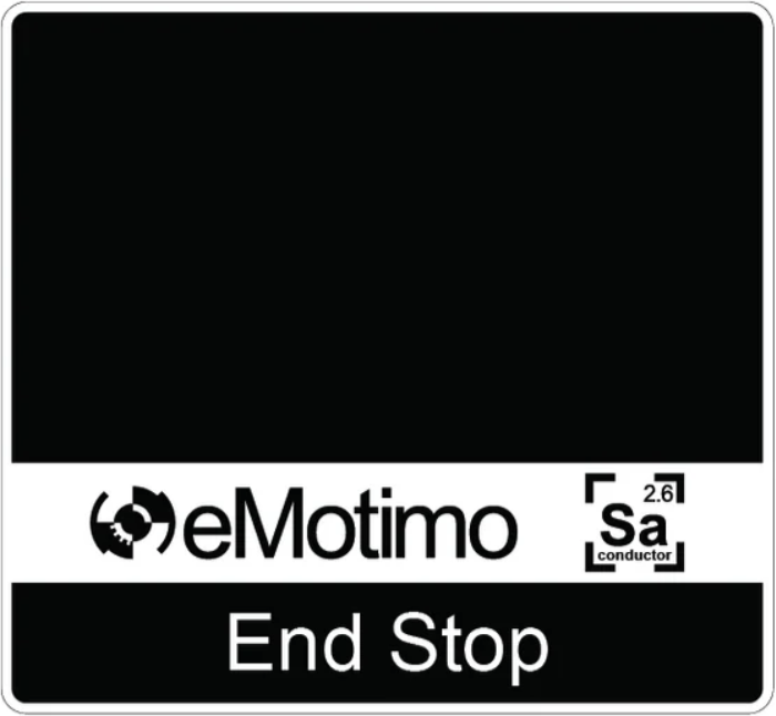
End stop markers tell the motion controller where the ends of the track are.
End stop markers are not physical stops! Install physical stops at both ends of the track to prevent the dolly/carriage from falling off if the system fails.
Mid point marker
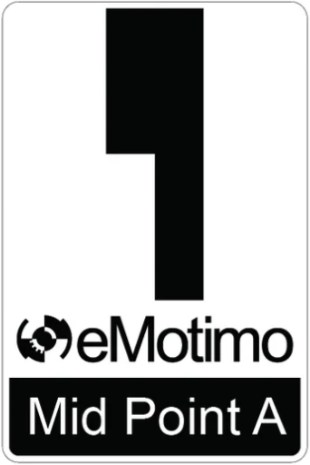
Mid point markers allow the motion controller to correct for slip in the drive wheel. The dolly should pass over at least one mid point marker during each loop.
Each mid point marker must line up with the center of the sensor assembly so the sensors can read its black regions. Align the markers as shown for your kit below. Start by placing one mid point marker at the center of the track, halfway along its length.
The mid point marker beside Home is the reference marker, the primary marker the motion controller uses as a reference. You will set Home beside your chosen reference marker during calibration in 2.3.
If you have a long track or plan to use loops that do not cross the center marker, add more mid point markers in the areas where those loops will run so each loop passes over at least one marker.
Install the markers for your kit
Follow the instructions for your integration kit below. Complete the sensor mounting and clean-track checks in 2.1 first. An end stop marker is the sticker read by the sensors; a physical end stop is the mechanical barrier. Position the sticker far enough inward to leave the required travel beyond it before the dolly reaches that barrier. Measure from the marker’s outer edge to the sensor’s sensing position.
Dana Dolly V3 Beltless Integration Kit marker placement
- Disengage the drive wheel or unplug the motor from your motion controller so you can move the dolly by hand.
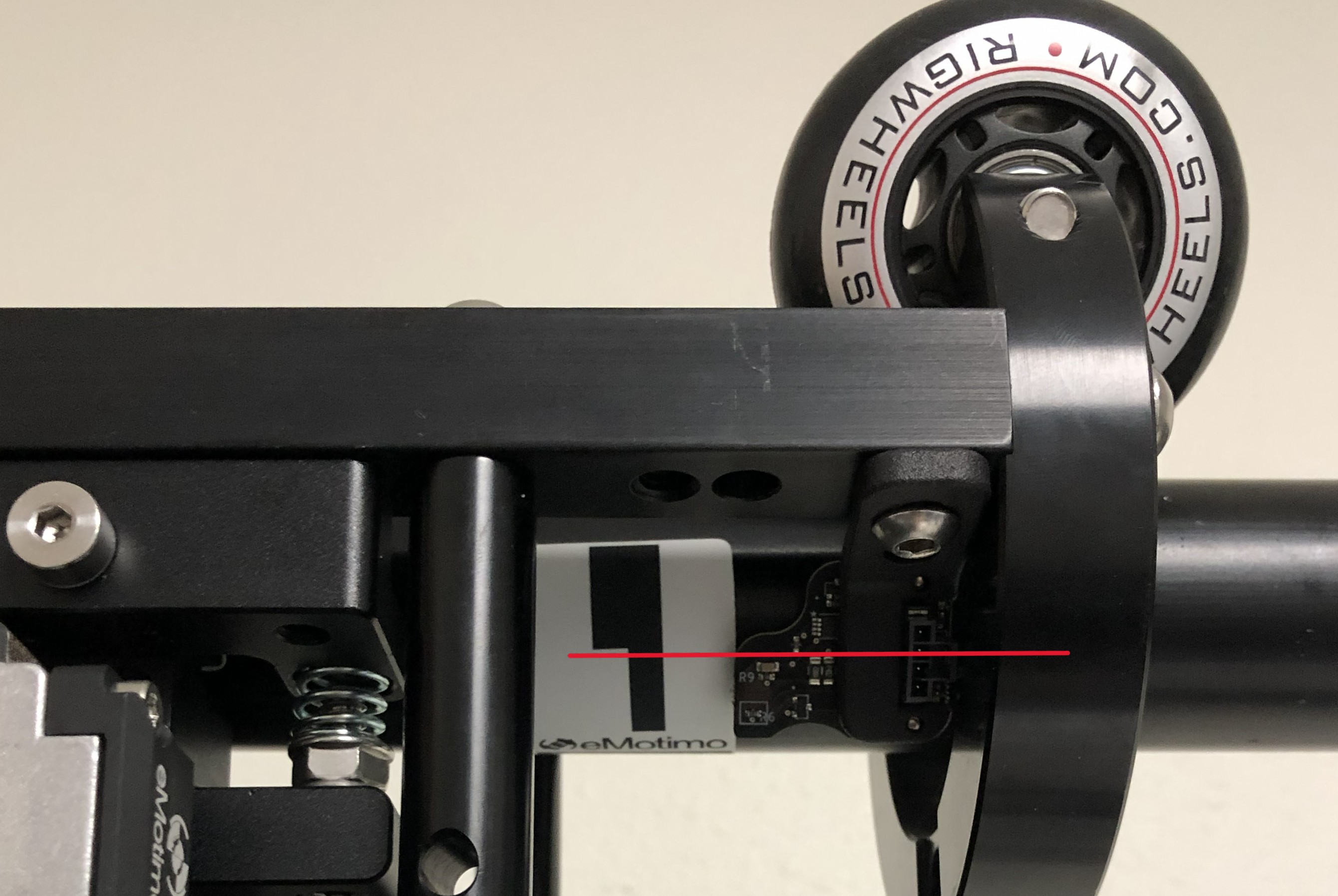
- Place one mid point marker halfway along the track. Align the marker’s centerline with the top of the rail, so it sits midway between the two sensors.
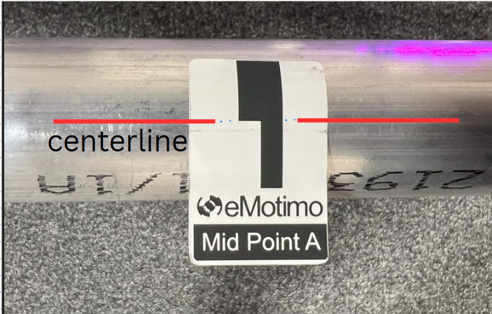
The red line marks the rail centerline through the marker.
Press each sticker firmly against the rail, making sure all edges lie flat.
Install the end stop stickers
- Place one end stop sticker near each end of the track, aligned so both sensors pass over its black area as the dolly moves along the rail. Position the left sticker at least 10 inches (26 cm) inward from the left end and the right sticker at least 8 inches (20 cm) inward from the right end.
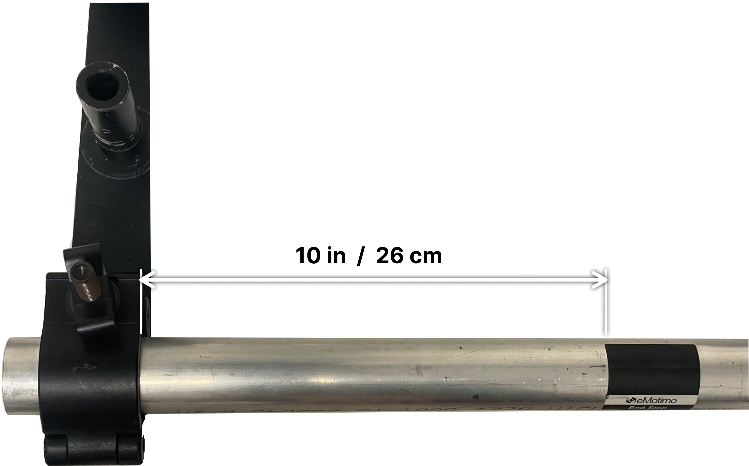
Left end marker placement
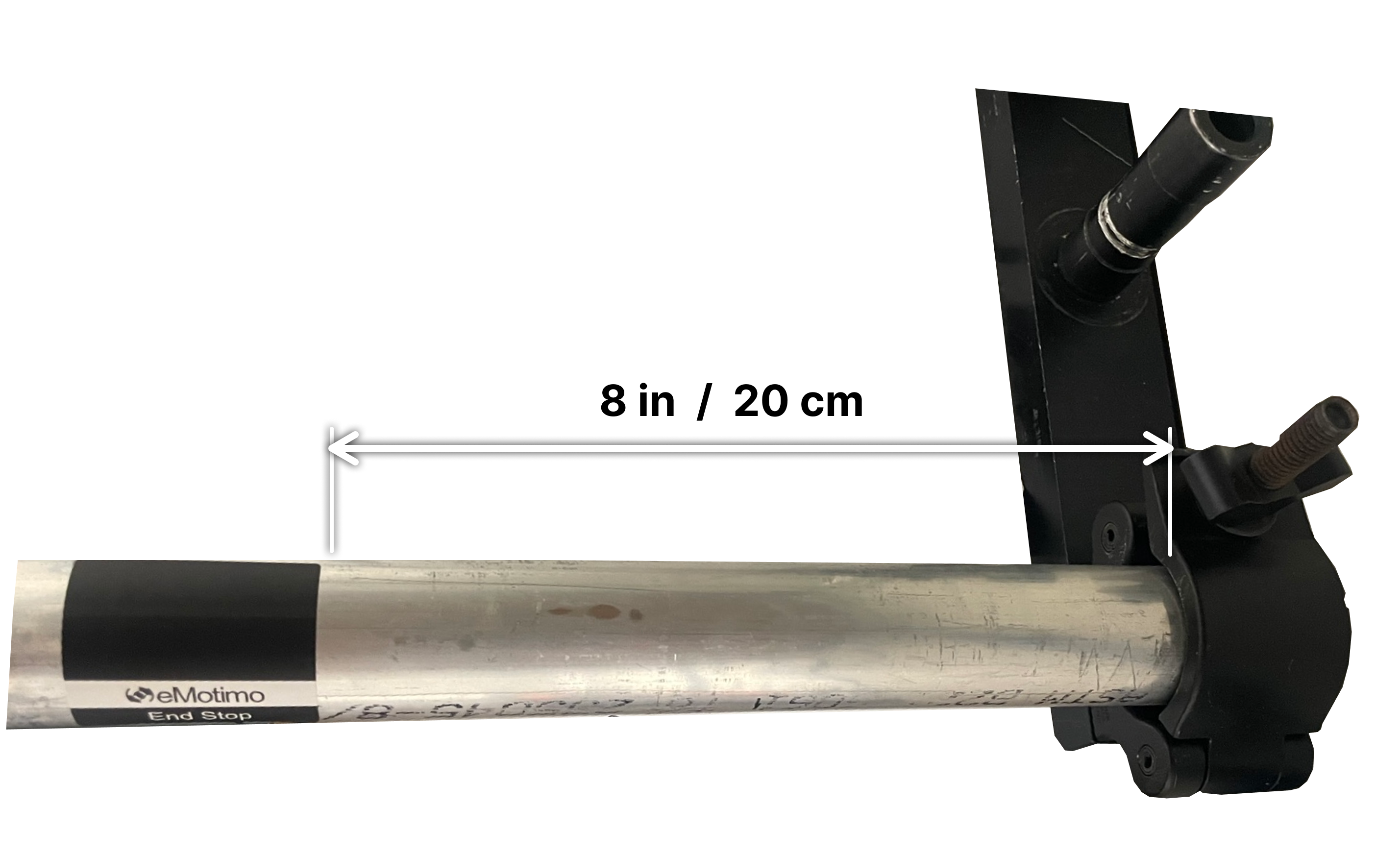
Right end marker placement
- At each end, move the dolly by hand to check that the sensor can cross the entire sticker and travel about 2 inches (5 cm) beyond its outer edge while the dolly remains clear of the physical end stop. Move the sticker inward if needed.
RigWheels Passport and RailDolly Integration Kit marker placement
- Disengage the drive wheel or unplug the motor from your motion controller so you can move the dolly by hand.
- Place one mid point marker halfway along the track. Align the marker’s centerline with the top of the rail, so it sits midway between the two sensors.
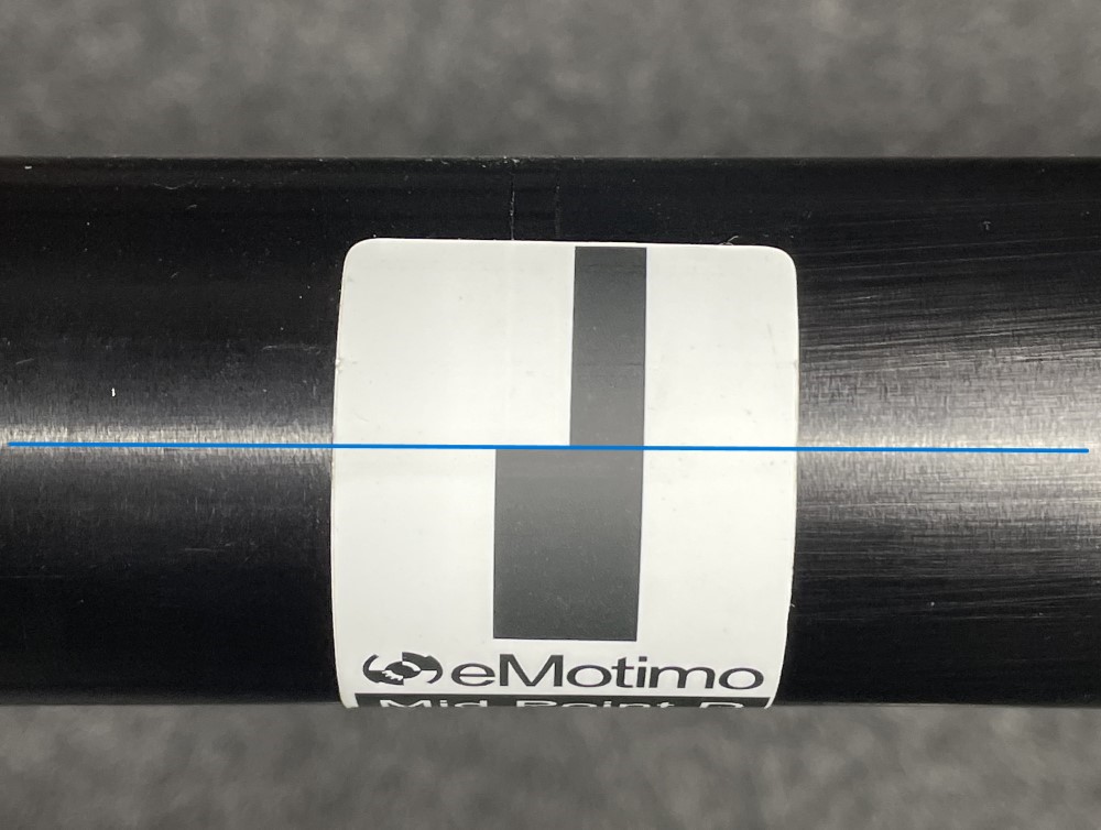
The blue line marks the rail centerline through the marker.
Press each sticker firmly against the rail, making sure all edges lie flat.
- Place one end stop sticker on top of the rail at each end of the track, aligned so both sensors pass over its black area as the dolly moves along the rail. Use 9 inches (23 cm) at the left end and 6 inches (15 cm) at the right end as starting offsets, following the measurement references shown in the photos below.
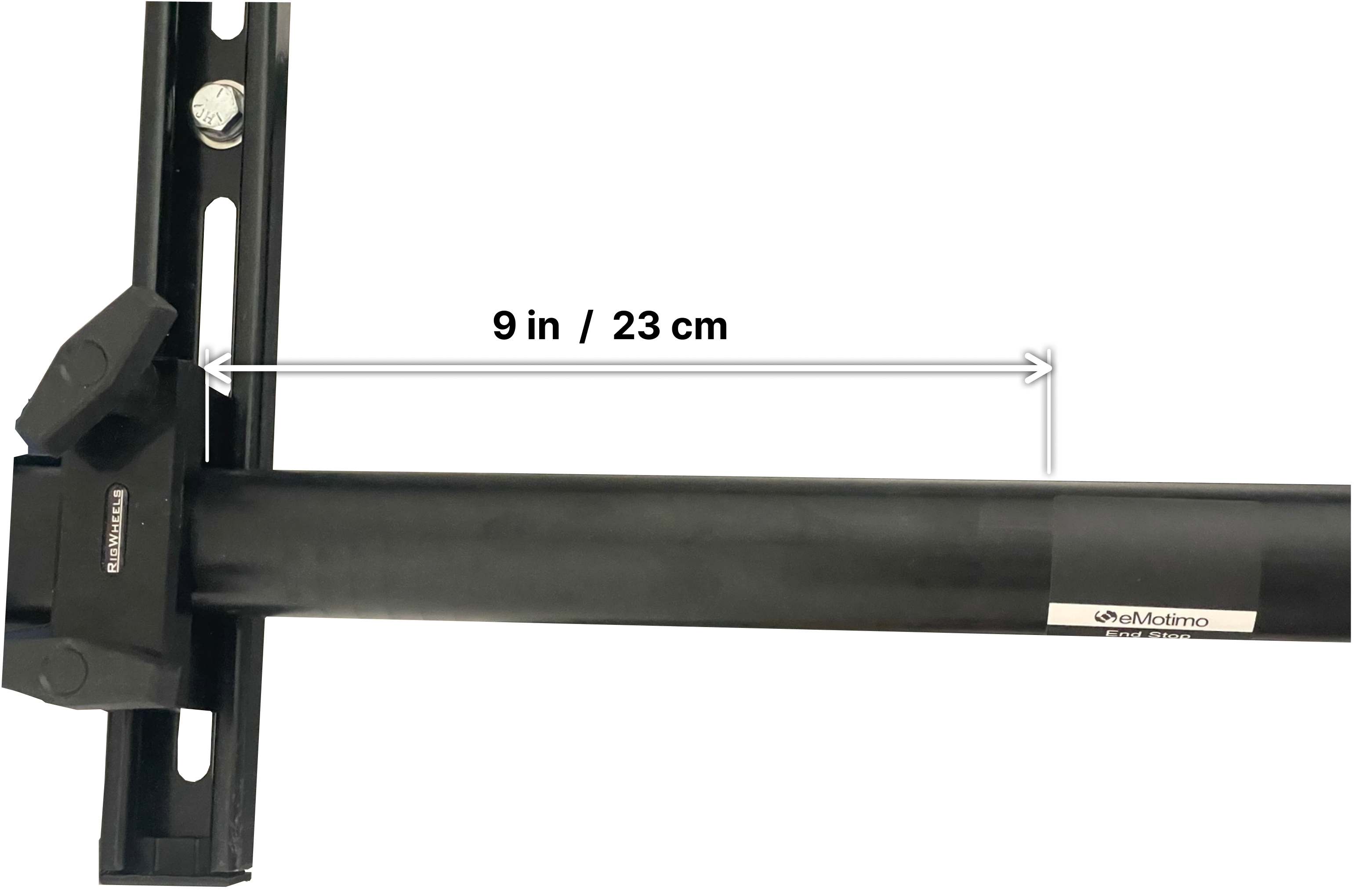
Left end marker placement on PortaRail.
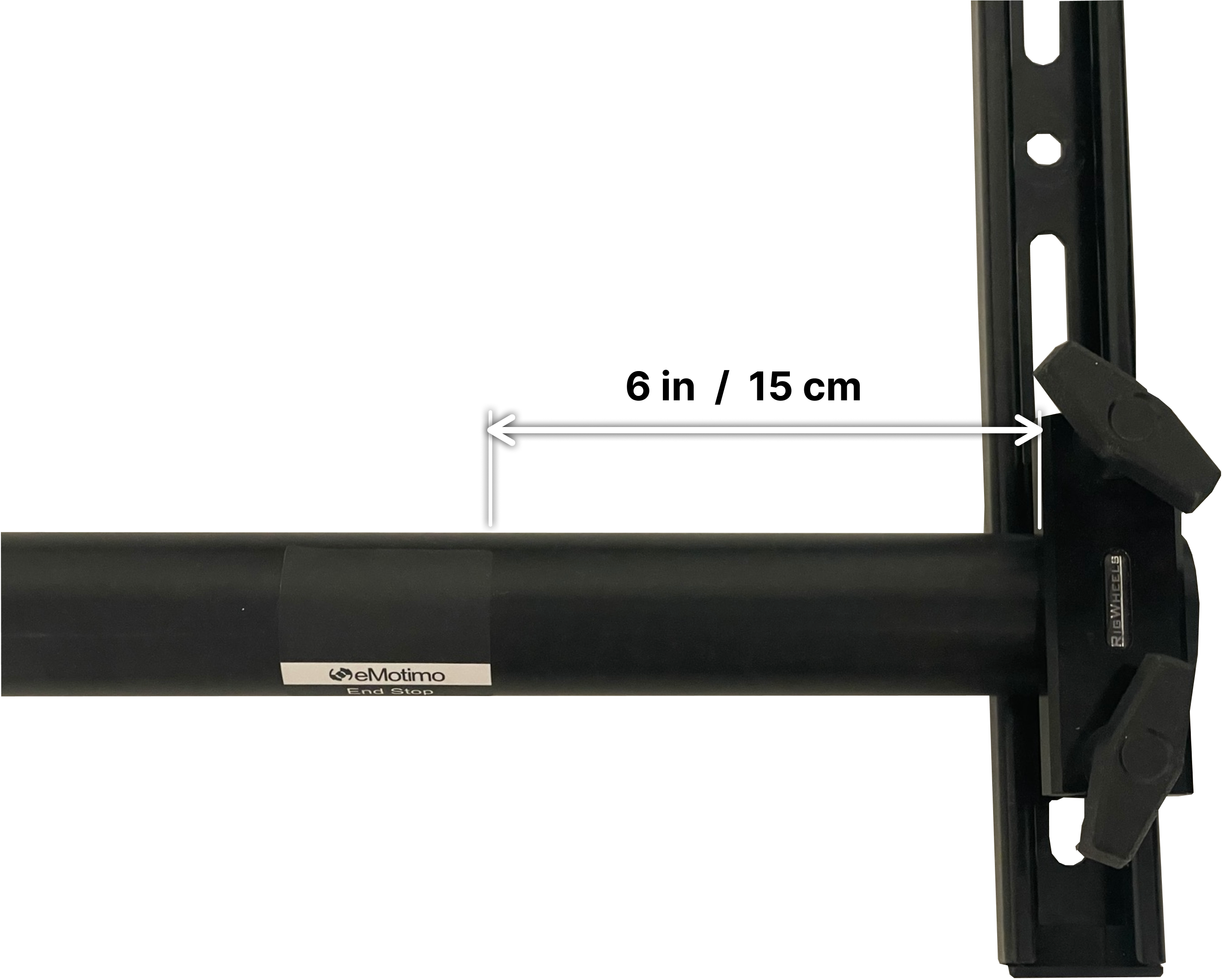
Right end marker placement on PortaRail.
- At each end, move the dolly by hand to check that the sensor can cross the entire sticker and travel about 2 inches (5 cm) beyond its outer edge while the dolly remains clear of the physical end stop. Move the sticker inward if needed.
RigWheels Monorail Integration Kit
Identify your sensor: In the photo below, V1 (left) has a rectangular sensor board, while V2 (right) has a sensor board with rounded edges.
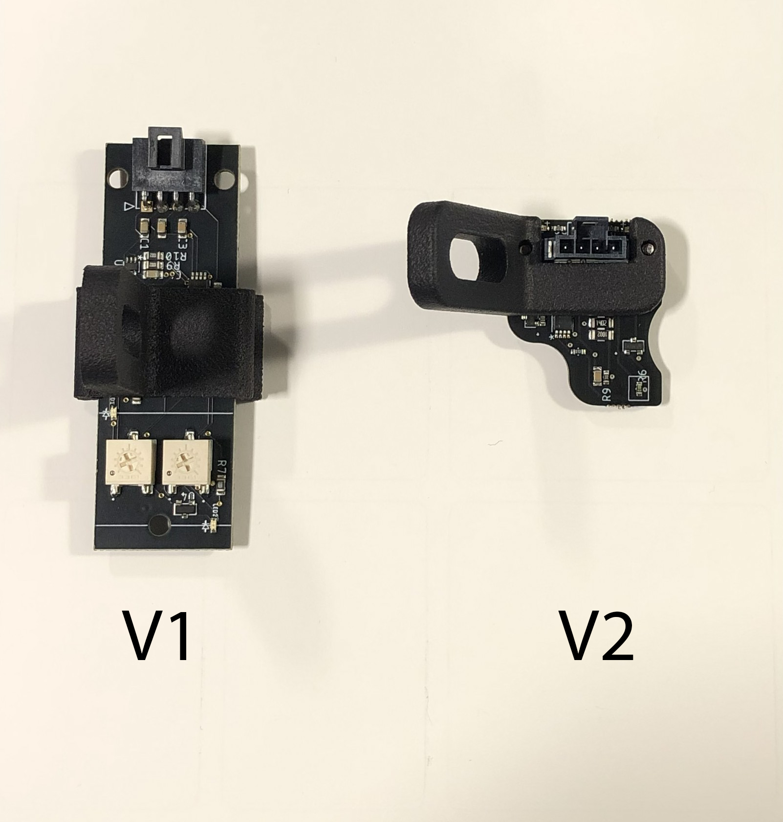
V1 sensor marker mounting
- Disengage the drive wheel or unplug the motor from your motion controller so you can move the dolly by hand.
- If moving the Monorail by hand is inconvenient, leave the motor engaged and plugged in. Navigate to Live Motion, then use the left stick on the included gaming remote to drive the Monorail along the track.
- Place one mid point marker halfway along the track. Position the marker on the side of the rail facing the sensor, aligning its centerline with the center of the sensor board.
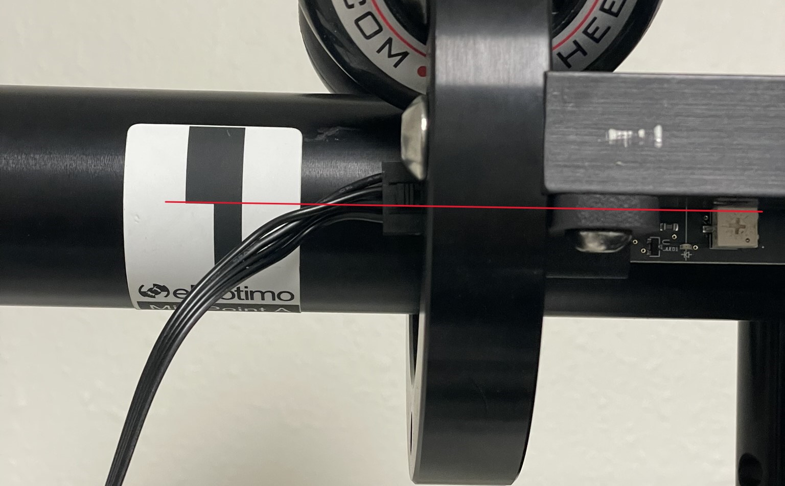
- Place one end stop sticker on top of the rail at each end of the track, aligned so both sensors pass over its black area as the dolly moves along the rail. Use 6 inches (15 cm) at the left end and 12 inches (30 cm) at the right end as starting offsets, following the measurement references shown in the photos below.
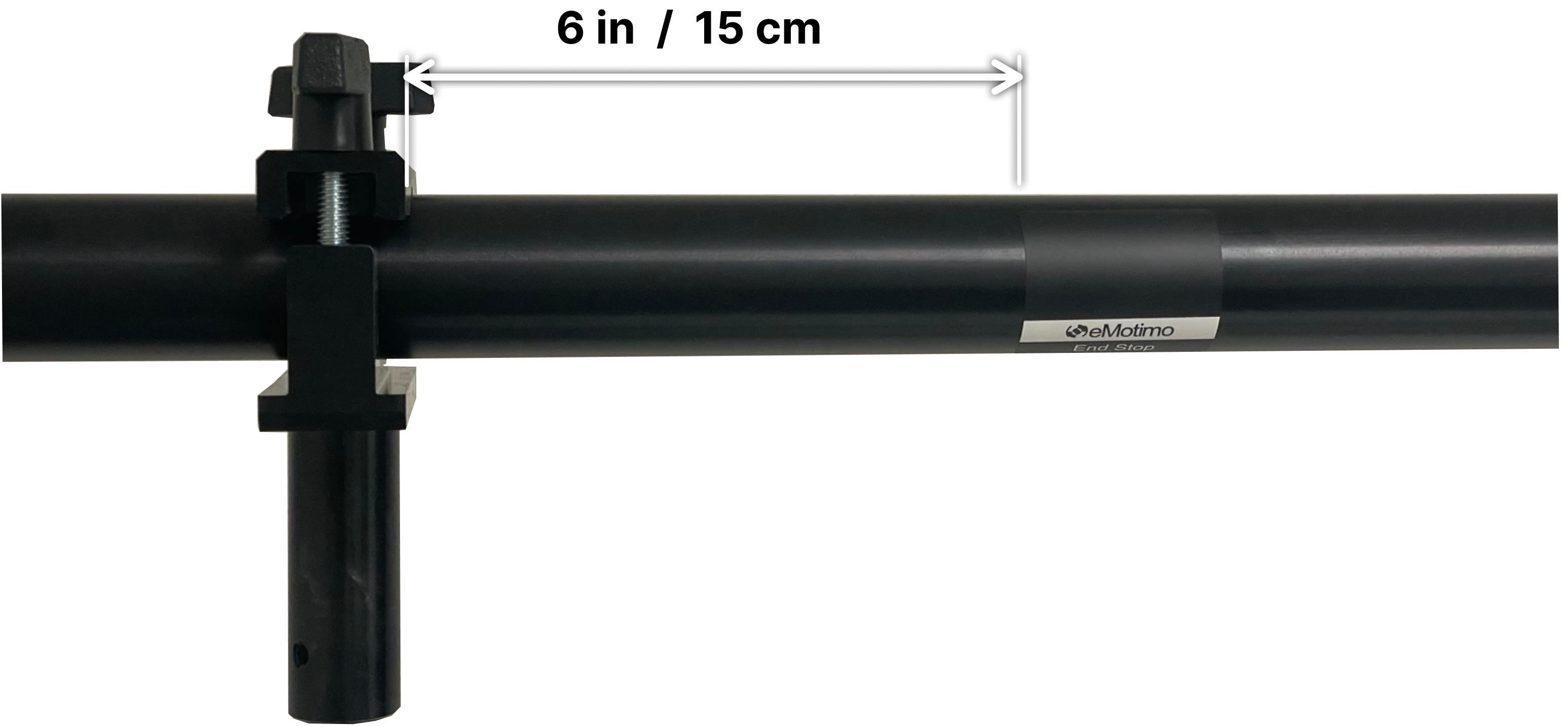
Left end marker placement on PortaRail.
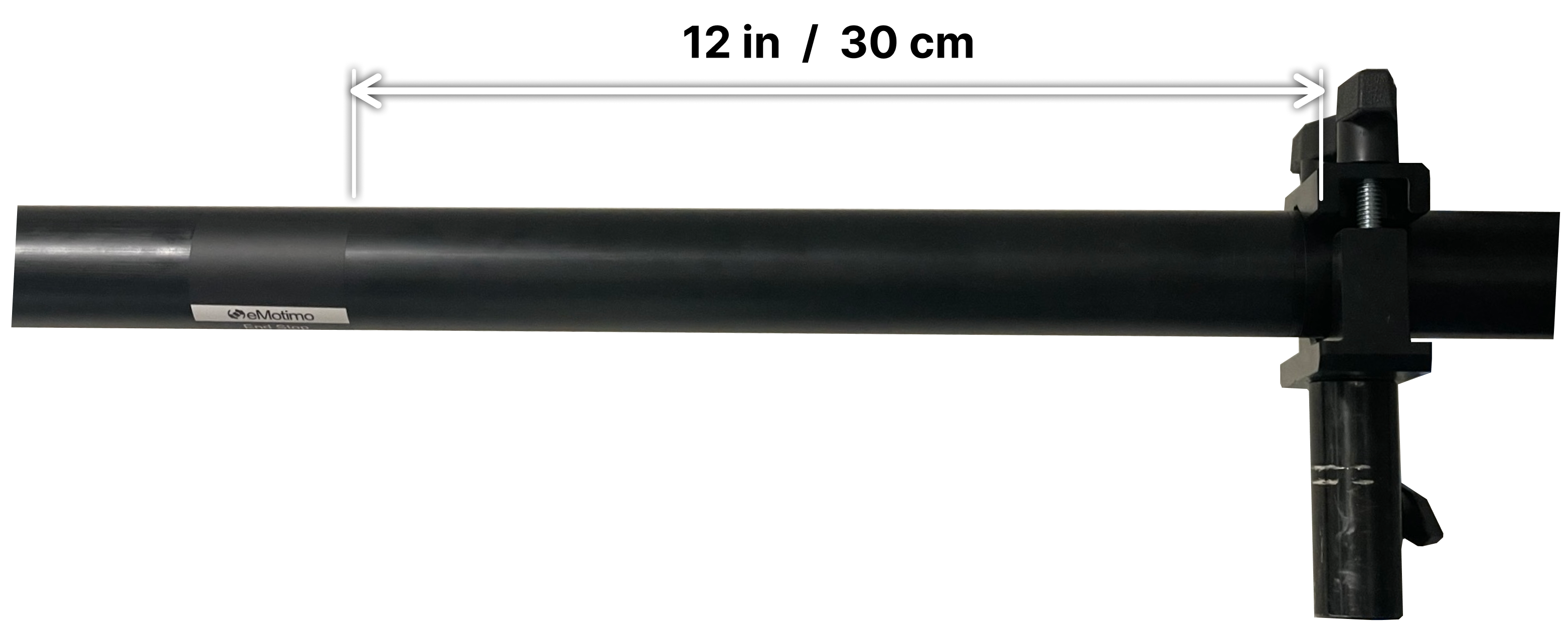
Right end marker placement on PortaRail.
- At each end, move the dolly by hand to check that the sensor can cross the entire sticker and travel about 2 inches (5 cm) beyond its outer edge while the dolly remains clear of the physical end stop. Move the sticker inward if needed.
V2 sensor marker mounting
- Disengage the drive wheel or unplug the motor from your motion controller so you can move the dolly by hand.
- If moving the Monorail by hand is inconvenient, leave the motor engaged and plugged in. Navigate to Live Motion, then use the left stick on the included gaming remote to drive the Monorail along the track.
- Place one mid point marker halfway along the track. Position the marker on the side of the rail facing the sensor, aligning its centerline with the center of the sensor board.
- Place one end stop sticker on top of the rail at each end of the track, aligned so both sensors pass over its black area as the dolly moves along the rail. Use 14 inches (36 cm) at the left end and 5 inches (13 cm) at the right end as starting offsets, following the measurement references shown in the photos below.
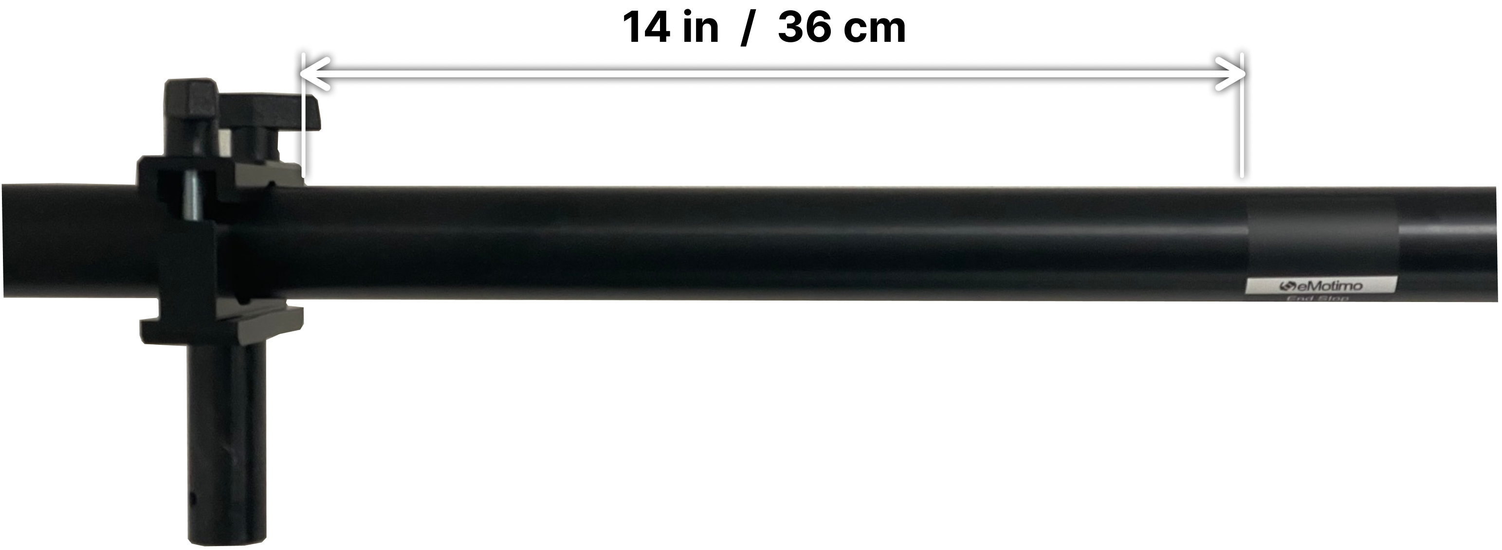
Left end marker placement on PortaRail.
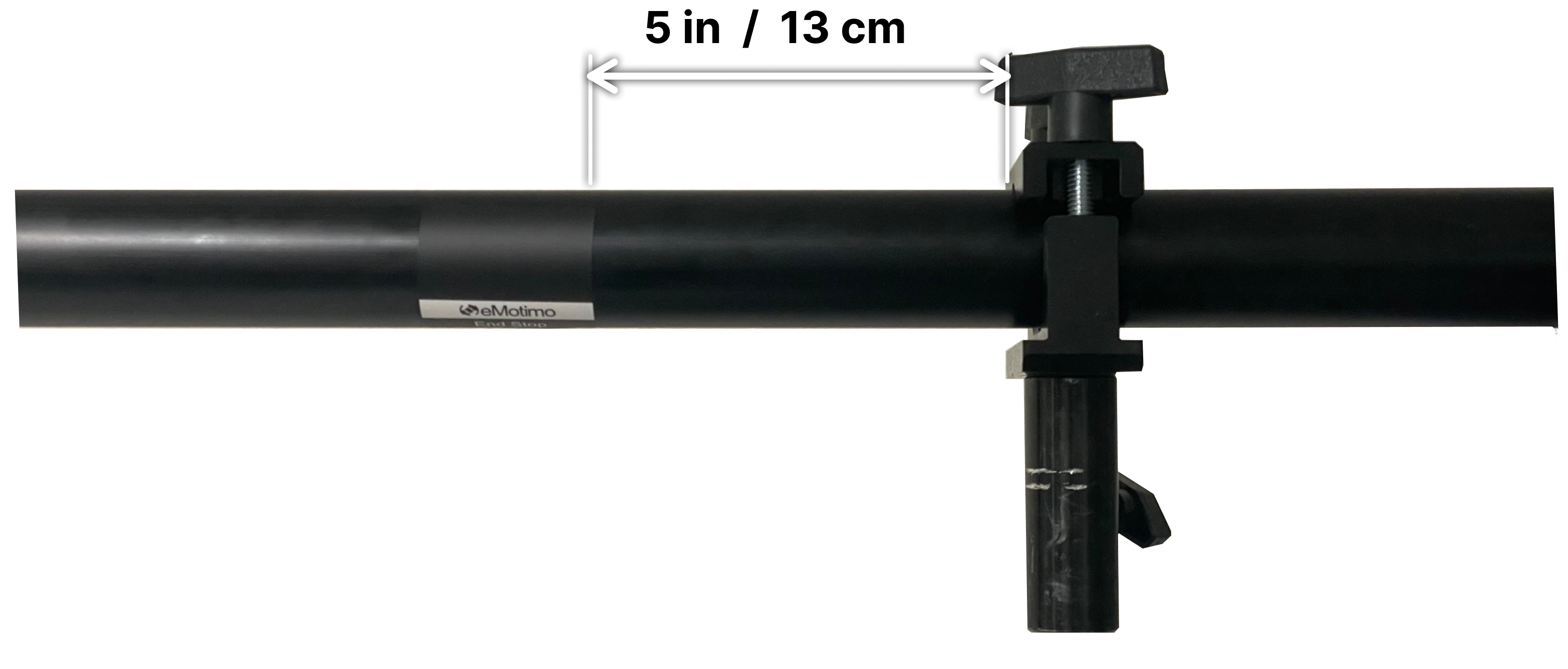
Right end marker placement on PortaRail.
- At each end, move the dolly by hand to check that the sensor can cross the entire sticker and travel about 2 inches (5 cm) beyond its outer edge while the dolly remains clear of the physical end stop. Move the sticker inward if needed.
Check marker detection
Manually move the dolly along the whole length of the track.
| Location | Expected response |
|---|---|
| Clean rail | Both LEDs off. |
| Crossing each end marker | Red and green on together over the black area, then both off after both sensors have fully cleared it onto clean rail. Check the complete crossing in both directions. |
| Beyond each end marker | The sensor assembly can travel about 2 inches (5 cm) beyond the outer edge of the end marker. |
| Mid point marker | The green and red LEDs should illuminate independently. |
If a check fails
- Flickering on clean rail: repeat the checks in 2.1 Prepare the track and install sensors.
- Only one sensor responds: repeat the checks in 2.1 Prepare the track and install sensors.
- Insufficient travel beyond the end stop marker: move the marker farther inward so the sensor assembly can cross it completely and travel about 2 inches (5 cm) beyond its outer edge, with the dolly still supported and clear of the physical stop. Repeat the full manual crossing and return pass at both ends before calibration.
- Scraping: raise the sensor only enough to prevent contact with the track. Confirm that it still reliably distinguishes the reflective track from the non-reflective markers.