2.1 Prepare the track and install sensors
The eMotimo Track Sensor System is a key technology in our motorized dolly systems that enables Power on Positioning. Properly setting up the sensors and markers is crucial for successfully configuring your eMotimo Broadcast system.
Before you begin
Follow the corresponding guide for installing your linear integration kit motor pod to the dolly/carriage:
- Dana Dolly V3 Beltless Integration Kit
- RigWheels Passport/RailDolly Integration Kit
- RigWheels Monorail Integration Kit
Have the dolly/carriage, track, and marker stickers available.
Check the sensors and track
The sensors detect markers by measuring reflected light. The track reflects light, while the black areas of the marker stickers reflect very little. As the dolly passes over a marker, the sensors detect this change. Keeping the track clean and reflective helps the sensors distinguish the markers from the surrounding track.
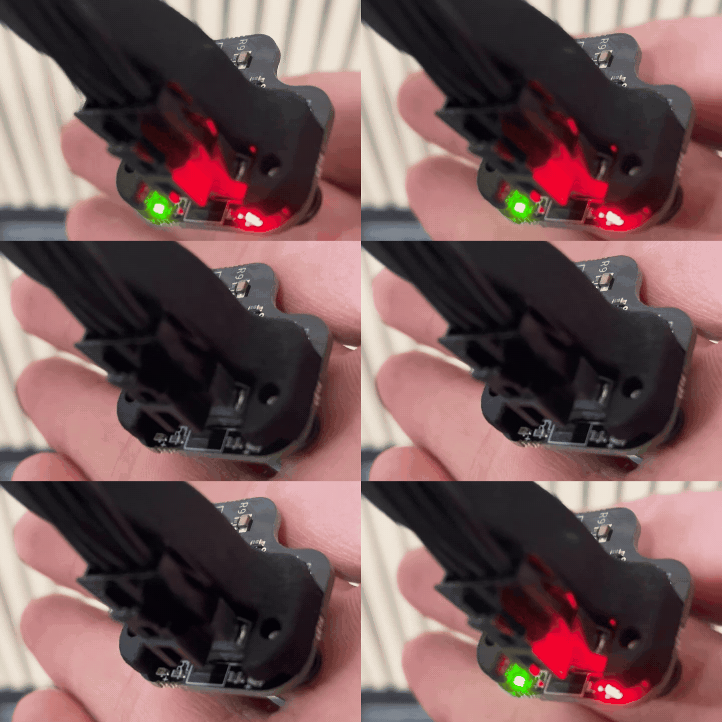
- Before mounting the sensor on the dolly, plug it into the motion controller. Move your hand toward and away from the sensors while watching the LEDs. The LEDs should turn off when your hand is close to the sensors and turn on when you move it away.
- Mount the sensor to the dolly following the corresponding guide.
Dana Dolly V3 Beltless Integration Kit sensor mounting
- Loosely attach the board to the DDV3 integration kit with the single M4 screw. The plastic channel on the sensor mount should contact the metal carriage mount, with the wires facing outward.
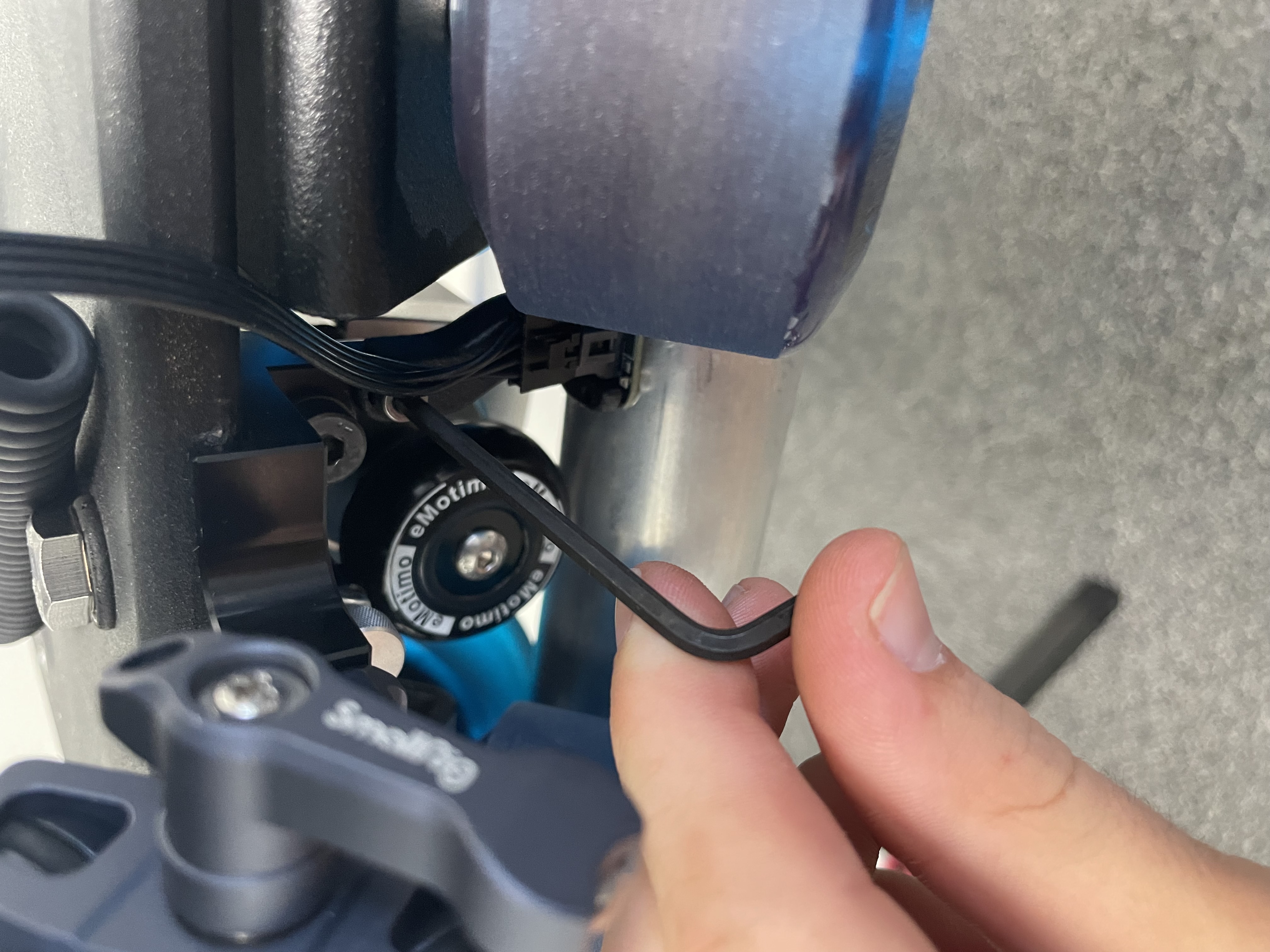
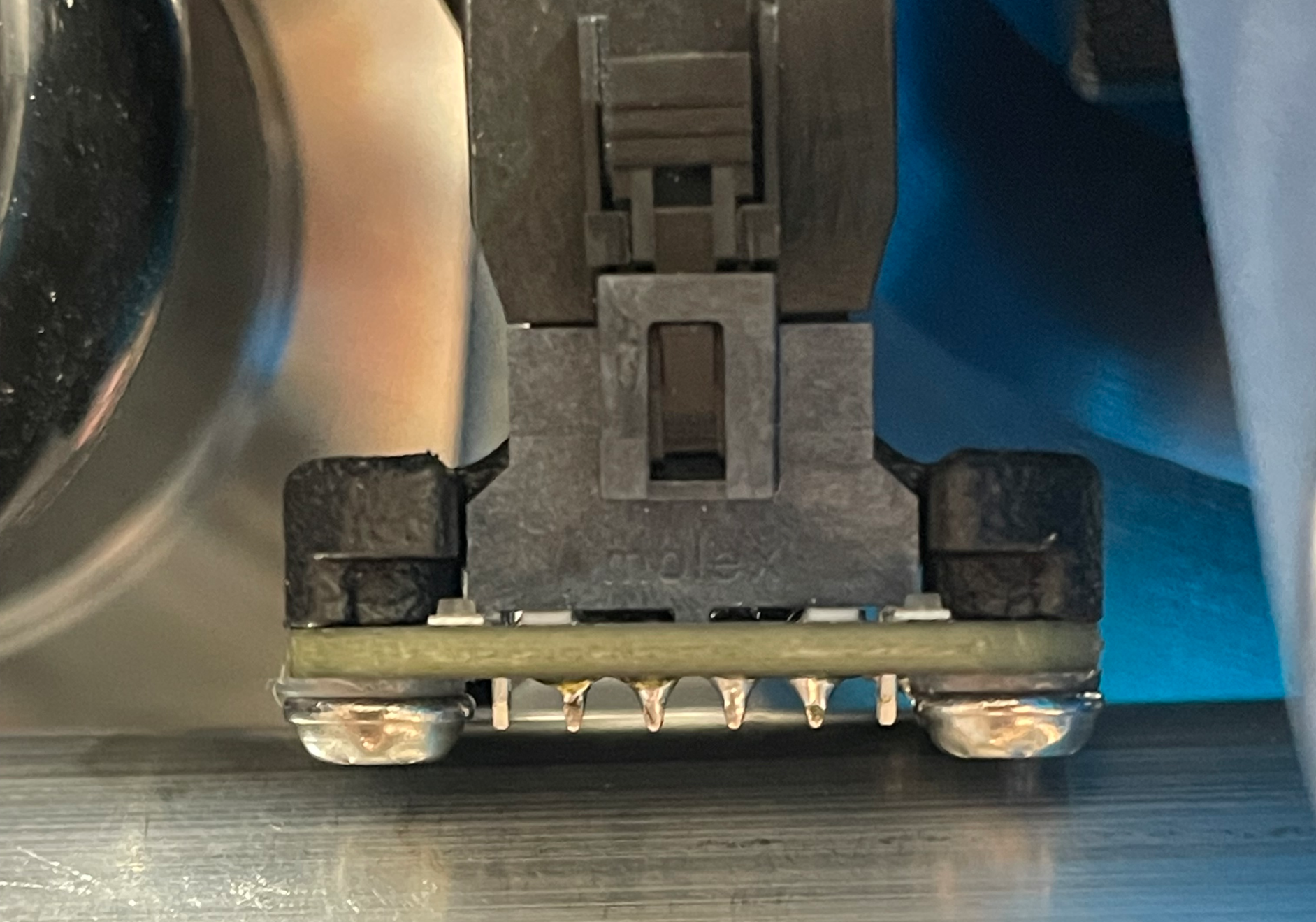
- Position the board parallel to the track with 1 mm between the sensors and the track, as shown in the close-up photo below. Keep the board and screws clear of the rail. Lightly tighten the screw.
- Disengage the drive wheel or unplug the motor from the motion controller, and move the dolly by hand along the clean track. Check that nothing contacts the rail and that both LEDs remain off throughout travel.
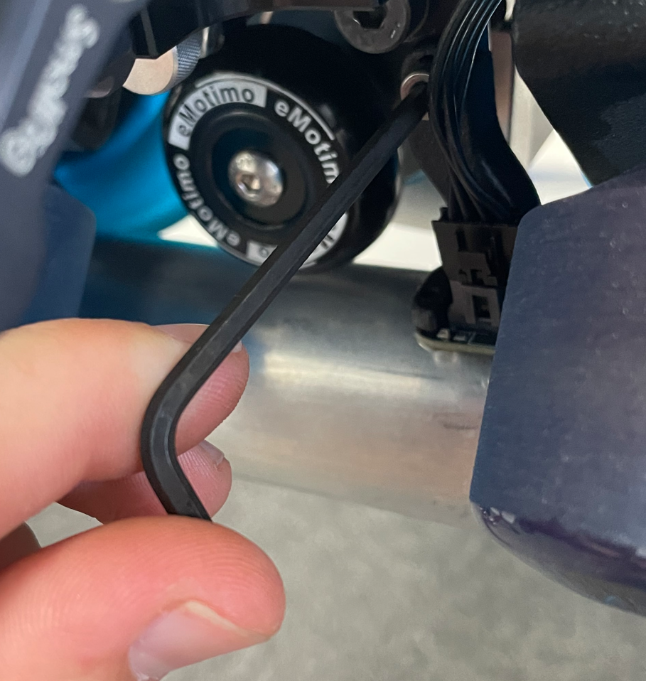
- Lightly tighten the screw to hold the position. The plastic stalk can break if overtightened; hold the short end of the wrench to limit force.
RigWheels Passport and RailDolly Integration Kit sensor mounting
- Loosely attach the board to the Passport or RailDolly integration kit with the single 1/4-20 screw. The raised region of the plastic sensor mount should fit into the metal channel of the carriage mount, with the wires facing outward.
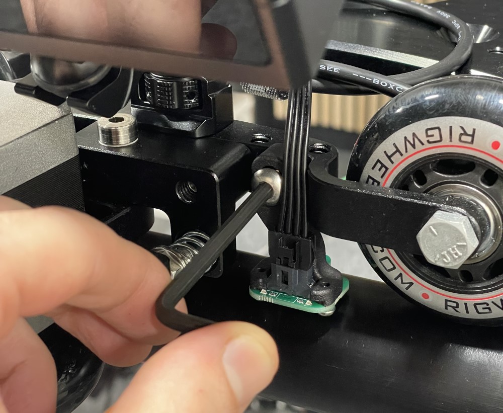
- Position the board parallel to the track with 1 mm between the sensors and the track, as shown in the close-up photo below. Keep the board and screws clear of the rail and marker stickers. Lightly tighten the screw.
- Disengage the drive wheel or unplug the motor from the motion controller, and move the dolly by hand along the clean track. Check that nothing contacts the rail and that both LEDs remain off throughout travel.
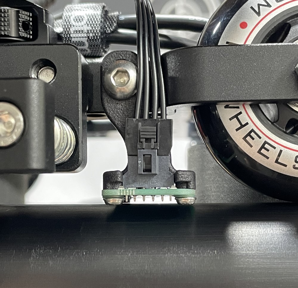
- Lightly tighten the screw to hold the position. The plastic stalk can break if overtightened; hold the short end of the wrench to limit force.
RigWheels Monorail Integration Kit sensor mounting
Identify your sensor: In the photo below, V1 (left) has a rectangular sensor board, while V2 (right) has a sensor board with rounded edges.
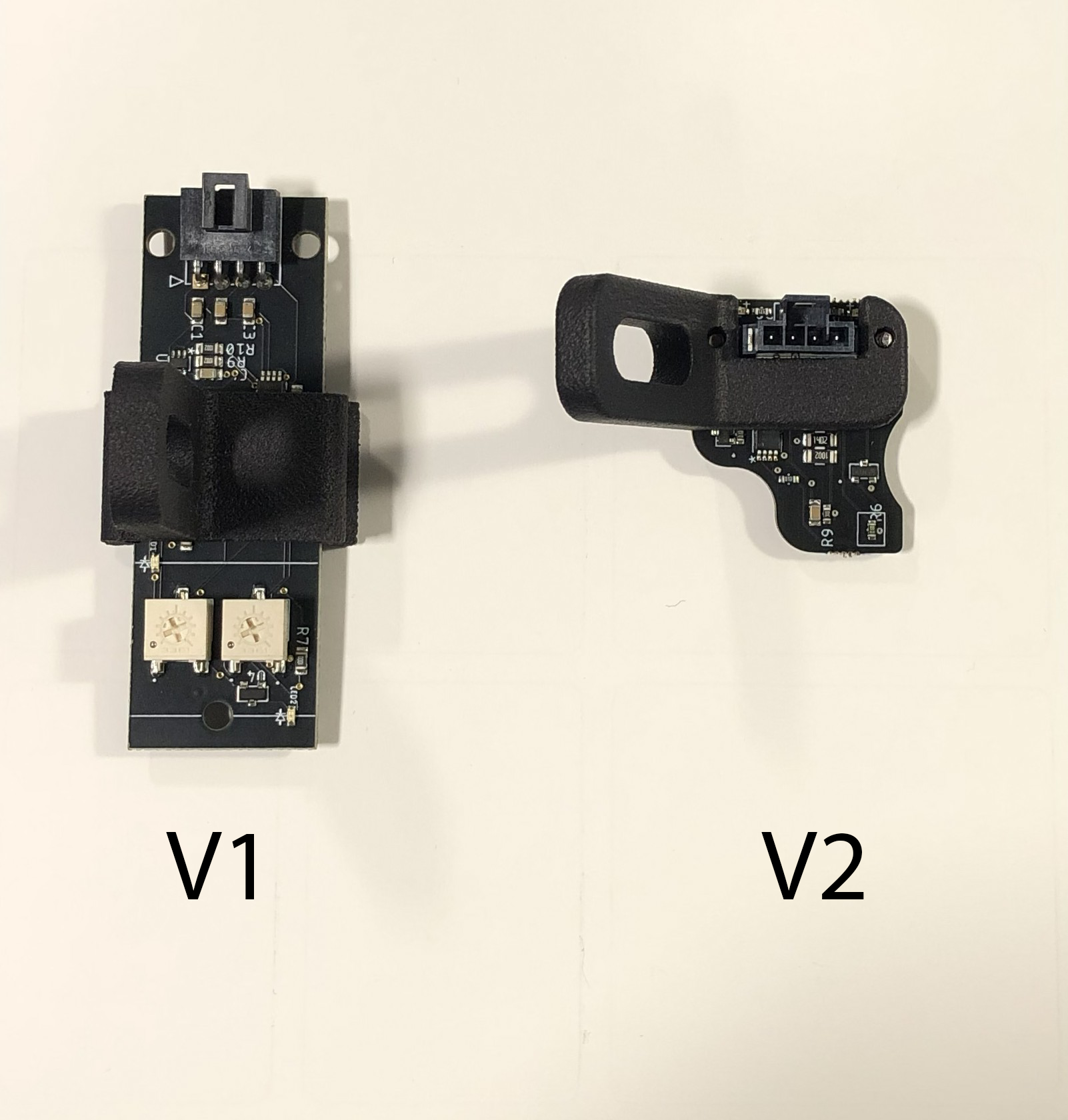
Use the mounting instructions for your sensor version below.
V1 sensor mounting
- Loosely attach the sensor to the left of the motor pod using the short 1/4-20 inch bolt.
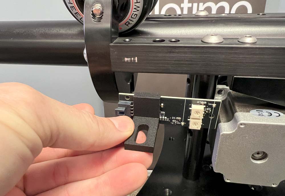
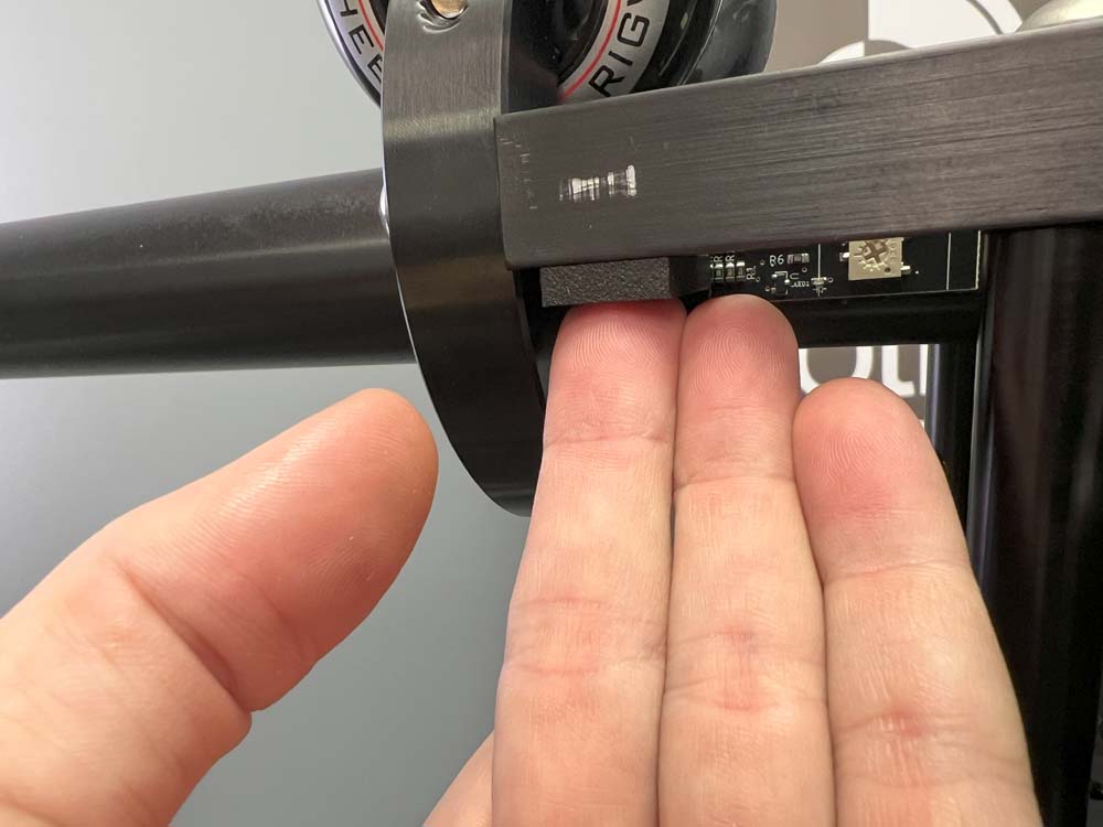
- Position the board parallel to the track and evenly spaced left to right, as shown in the closeup photos below. Keep the board and screws clear of the rail. Lightly tighten the mounting screw or bolt.
- V1: Leave about 1 mm between the bottom sensor and the rail.
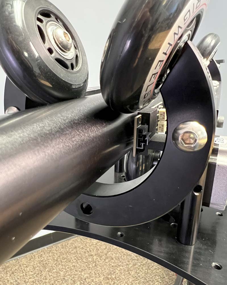
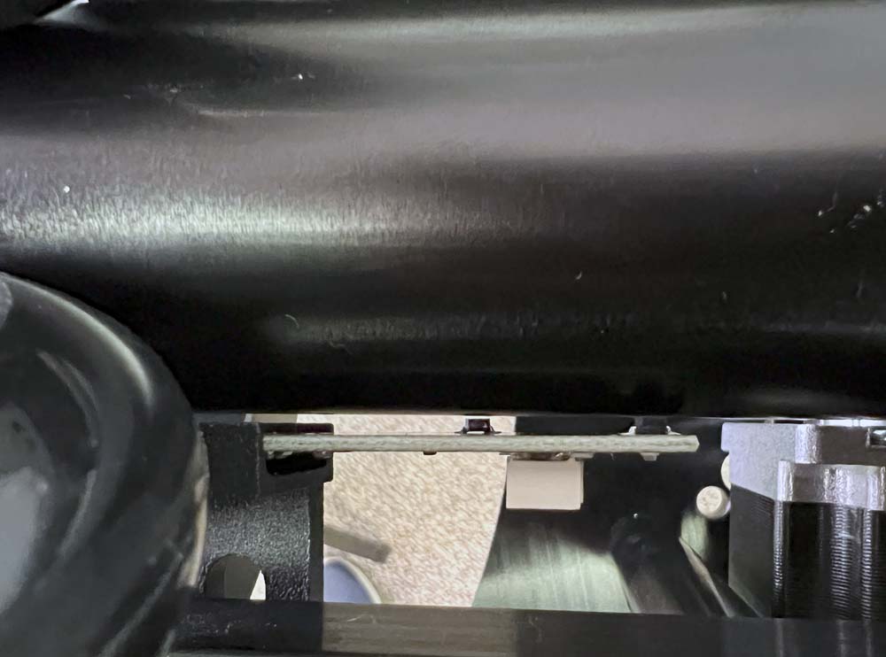
- Disengage the drive wheel or unplug the motor from the motion controller, and move the Monorail by hand along the clean track. Check that nothing contacts or scrapes the rail and that both LEDs remain off throughout travel. Readjust if anything touches the rail, or the LEDs aren’t consistently off along the length of the track.
- If moving the Monorail by hand is inconvenient, leave the motor engaged and plugged in. Navigate to Live Motion, then use the left stick on the included gaming remote to drive the Monorail along the track.
- Lightly tighten the mounting screw or bolt to hold the position. The plastic mount can crack if overtightened; hold the short end of the wrench to limit force.
V2 sensor mounting
- Loosely attach the sensor to the right of the motor pod using the short 1/4-20 inch bolt.
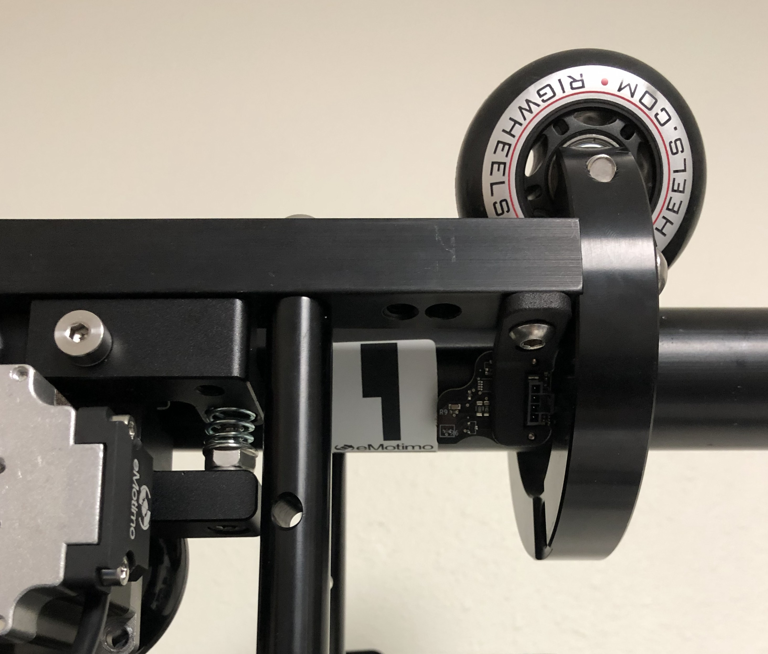
- Position the board parallel to the track and evenly spaced left to right, as shown in the closeup photos below. Keep the board and screws clear of the rail. Lightly tighten the mounting screw or bolt.
- V2: Bring the bottom sensors close to the rail without letting the board or screws touch it.
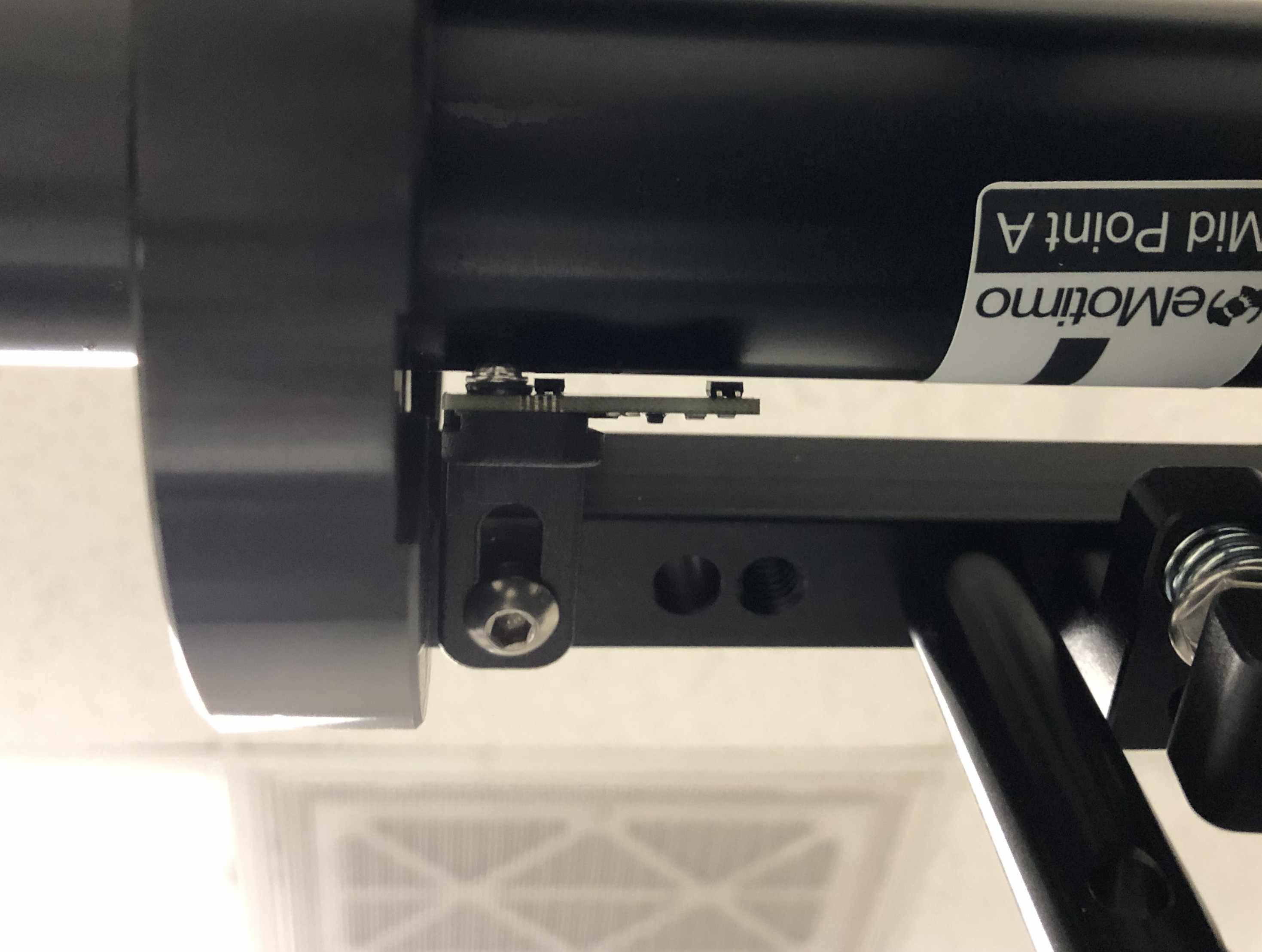
- Disengage the drive wheel or unplug the motor from the motion controller, and move the Monorail by hand along the clean track. Check that nothing contacts or scrapes the rail and that both LEDs remain off throughout travel. Readjust if anything touches the rail, or the LEDs aren’t consistently off along the length of the track.
- If moving the Monorail by hand is inconvenient, leave the motor engaged and plugged in. Navigate to Live Motion, then use the left stick on the included gaming remote to drive the Monorail along the track.
- Lightly tighten the mounting screw or bolt to hold the position. The plastic mount can crack if overtightened; hold the short end of the wrench to limit force.
Sensor troubleshooting
| LED behavior | Meaning or action |
|---|---|
| 🟢 Correct: Both LEDs are off along the whole length of track. | Good. That means your track is reflective and your sensor is properly mounted. |
| 🟠 Needs adjustment: The LEDs flicker along the length of the track. | Try mounting the sensor closer to the track without contacting it. If your track has scrapes which are causing the flickering, try polishing the track with a fine grit sand paper/brillo pad (not recommended for black anodized track). |
| 🟠 Needs adjustment: One LED flickers/is illuminated along the length of the track while the other is off. | Make sure the sensor board is parallel with the track. |
✅ You can move on when both LEDs remain off for the full length of the track as you move the dolly or carriage.